|
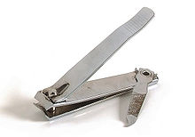
Compound lever The compound lever is a simple machine operating on the premise that the resistance from one lever in a system of levers acts as effort for the next, and thus the applied force is transferred from one lever to the next. Almost all scales use some sort of compound lever to work. Other examples include nail clippers and piano keys. Mechanical advantageA lever arm uses the fulcrum to lift the load using and intensifying an applied force. In practice, conditions may prevent the use of a single lever to accomplish the desired result,[1] e.g., a restricted space, the inconvenient location of the point of delivery of the resultant force, or the prohibitive length of the lever arm needed. In these conditions, combinations of simple levers, called compound levers, are used. Compound levers can be constructed from first, second and/or third-order levers. In all types of compound lever, the rule is that force multiplied by the force arm equals the weight multiplied by the weight arm. The output from one lever becomes the input for the next lever in the system, and so the advantage is magnified. The figure on the left illustrates a compound lever formed from two first-class levers, along with a short derivation of how to compute the mechanical advantage. With the dimensions shown, the mechanical advantage, W/F can be calculated as 10/3 × 9/4 = 7.5, meaning that an applied force of 1 pound (or 1 kg) could lift a weight of 7.5 lb (or 7.5 kg). Alternatively, if the position of the fulcrum on lever AA' were moved so that A1 = 4 units and A2 = 9 units, then the mechanical advantage W/F is calculated as 4/9 × 9/4 = 1, meaning that an applied force will lift an equivalent weight and there is no mechanical advantage. This is not usually the goal of a compound lever system, though in rare situations the geometry may suit a specific purpose.  The distances used in calculation of mechanical advantage are measured perpendicular to the force. In the example of a nail clipper on the right (a compound lever made of a class 2 and a class 3 lever), because the effort is applied vertically (that is, not perpendicular to the lever), distances to the respective fulcrums are measured horizontally, instead of along the lever. In this example, W/F is 7 + 1/1 × 6/6 + 2 = 6. Note that (7 + 1) cm = 8 cm is the distance from the point of application of the effort to the fulcrum of the first lever, perpendicular to the applied effort. Examples A few examples of the compound lever are the scale, train brakes, and a common type of nail clippers. Another example is the elbow-joint press, which is used in printing, molding or handloading bullets, minting coins and medals, and in hole punching. Compound balances are used to weigh heavy items. These all use multiple levers to magnify force to accomplish a specific purpose. The train brake translates the force of pushing back the stick to the levers and they rub against the wheels, using friction to slow and eventually stop the train. These are everyday applications of this mechanism.  A piano key is a compound lever of the first-class, since the fulcrum is between the weight to be moved and the power. The purpose of this lever is to translate a small movement (depression of the key) into a larger and fast movement of the hammer on the strings. The quality of the resulting tone depends on whether the final speed is brought about by gradual or sudden movement of the key.[2]  The malleus, incus and stapes are small bones (ossicles) in the middle ear, connected as compound levers, that transfer sound waves from the eardrum to the oval window of the cochlea. HistoryThe earliest remaining writings regarding levers date from the 3rd century BC and were provided by Archimedes. "Give me a place to stand, and I shall move the earth with a lever" is a remark attributed to Archimedes, who formally stated the correct mathematical principle of levers (quoted by Pappus of Alexandria).[3] One of the earliest examples of a compound lever is from Han dynasty (202 BC - 220 AD) crossbow trigger mechanisms which featured a triple compound lever. Such a mechanism was placed within the crossbow stock itself.[4] The idea of the compound lever is attributed to the Birmingham inventor John Wyatt in 1743,[5] when he designed a weighing machine that used four compound levers to transfer a load from a weighing platform to a central lever from which the weight could be measured.[6] References
|
